Stator core &
end-winding vibrations
Stator core
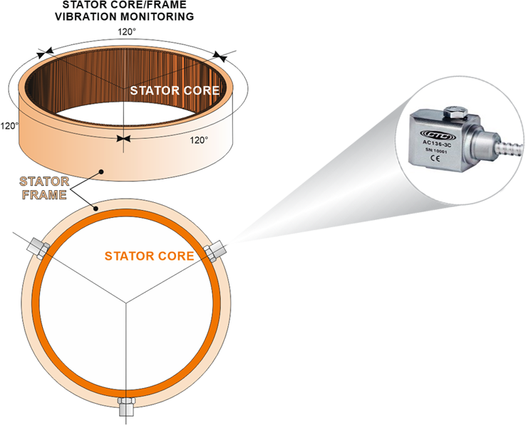
Stator core vibrations measurements are conducted using accelerometers or velocity meters positioned around the stator core, typically in radial directions on each segment.

Faults and conditions detected
Loose stator core (or segment joints)
Stator stiffness change in operation
Typical configuration
Accelerometers positioned around stator core (typically 3-6 sensors per unit)
CoDiS RT – on-line monitoring and protection instrument
CoDiS DM – on-line and off-line diagnostic software
On-line instrument
- CoDiS RT - Real time Protection unit
Diagnostic Modules
- CoDiS DM - Diagnostic Monitoring
END-WINDING
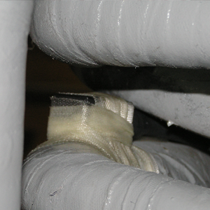
Stator end winding vibrations measurements are conducted using fiber optic accelerometers positioned around the stator core, typically in radial (also tangential) directions on end winding. Bump test is recommended to identify the best sensors location

Faults and conditions detected
Looseness of the end-winding support and tie structure due to mechanical aging and thermal expansion
Resonance conditions close to the primary mechanical forces of rotational frequency and twice the AC line frequency
Relative motion between one component and another which can abrade the high voltage insulation on the coils
Typical configuration
EVAII positioned around stator on end windings (typically 3-6/12 sensors per unit)
CoDiS RT – on-line monitoring and protection instrument
CoDiS DM – on-line and off-line diagnostic software
On-line Instrument
- CoDiS RT - Real time Protection unit
Diagnostic Modules
- CoDiS DM - Diagnostic Monitoring
